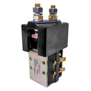
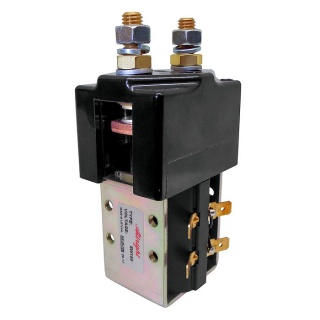
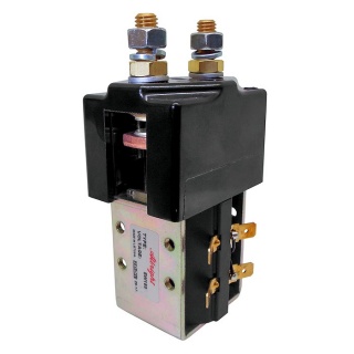
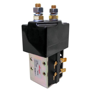
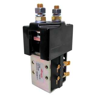
Albright International SW180B-646M magnetically latched single-acting 24VDC 150 Amps solenoid contactor with magnetic blowouts, continuous.
- The SW180B series of contactors has been designed for direct current loads, particularly motors, as used on small electric vehicles such as industrial trucks, airport tractors, etc. They have double-breaking contacts with Silver-alloy contact tips, which are weld-resistant, hardwearing and have excellent conductivity.
- The contactors are compact in size and are fully serviceable, with a range of spare parts available.
- Repair contact kit part number: 2180-42.
- Auxiliary switch kit part number: 2180-796.
- Mounting bracket available: 2159-47.
- Magnetic Latching version
Dimensions
- Height, including terminals and coil base cap: 122mm.
- Coil width: 45mm.
- Cap width: 61mm.
- Cap depth: 45mm.
Magnetic Blowouts
These contactors are of double break configuration and are fitted with magnetic blowouts (denoted by the 'B' suffix in the SW180B range) across both contact gaps. These enable high currents to be ruptured very quickly so that arcing time is reduced to a minimum. The fitting of blowouts makes the contacts polarity sensitive, and the positive markings on the top cover of the contactor must be observed.
About Continuous (CO.) SW180B Solenoids
Continuous contactors, by design, are predominantly used for drive functions on vehicles; they make and break slower than intermittent solenoids and are recommended for prolonged contact periods.
The SW180B has been designed for direct current loads, including motors, as used on electric vehicles such as industrial trucks. Developed for both interrupted and uninterrupted loads, the SW180B is suitable for switching Resistive, Capacitive and Inductive loads.
The SW180B features single-pole, single-throw, double-breaking main contacts with Silver-alloy tips, which are weld-resistant, hardwearing and have excellent conductivity. The SW180B has M8 stud main terminals and 6.3mm spade coil connections. It can be mounted via M5 tapped holes or steel mounting brackets (supplied as separate items). Mounting can be horizontal or vertical. When vertical, the M8 contact studs should point upwards.
Magnetic Latching: The contact position is secured with the use of a permanent magnet within the coil assembly. The coil requires a pulse(~500ms) to close the contacts, and a reverse polarity pulse (~500ms) to operate the armature and open the contacts, but otherwise remains in the last energised state without the need for power. It should be noted therefore these are not failsafe.
| Interrupted Current: The opening and closing on load with frequent switching (resulting in increased contact resistance). |
| Uninterrupted Current: No or infrequent load switching requirements (maintains a lower contact resistance). |
Specifications
| Device Type | NO - SP - ST |
| Voltage | 24V D.C. |
| Coil Type | Continuous |
| Amps | 150 Amps |
| Coil Resistance (Ohms) | 17 |
| Pull-In Voltage (V) | 12.0 Maximum. |
| Drop Out Voltage (V) | 12.0 Maximum. |
| Coil Power Dissipation (W) | 33.88 |
| Typical Pull-In Time | 30ms |
Typical Voltage Drop Per Pole
Across New Contacts At 100A | 30mV |
| Operating Ambient Temperature | -40 to +60℃ |
| Weight | 690g |
| Application | Uninterrupted |
| Thermal Current Rating | 150A |
| Intermittent Current Rating: |
| 30% Duty | 275A |
| 40% Duty | 240A |
| 50% Duty | 225A |
| 60% Duty | 200A |
| 70% Duty | 180A |

.jpg)
.jpg)
.jpg)
.jpg)
.jpg)
.jpg)
.jpg)
.jpg)
.jpg)
.jpg)
.jpg)
.jpg)
.jpg)
.jpg)
.jpg)
.jpg)
.jpg)