| 
Need help? Email us: sales1@arc-components.com

0-443-51 Durite 12V-24V R10 4-Bolt 4FT LED Light Bar

0-443-51 Durite 12V-24V R10 4-Bolt 4FT LED Light Bar
£499.85 Excl. VAT
RRP £585.58 Excl. VAT
(£599.82 Inc. VAT)
Initial Savings
£85.73
Earn 499 Loyalty Points
   
Available
UK Mainland Shipping Only
Model
0-443-51
Bar Code
5056119155204
Part Number
0-443-51
Brand
Durite
Colour
Amber
Voltage
12V/24V DC
Material
ABS/Polycarbonate/Copper
Shape
Rectangle
 Intrastat HS Code  8512200090
Ship Weight
9.80 kg
 

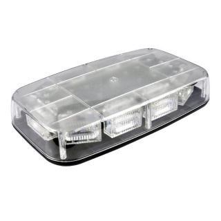
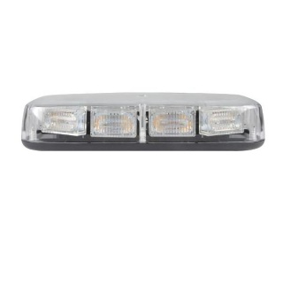
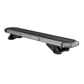
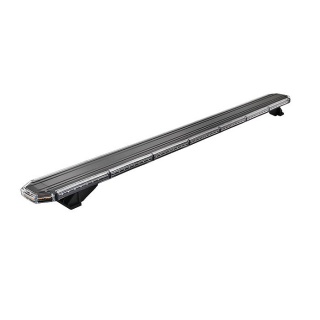
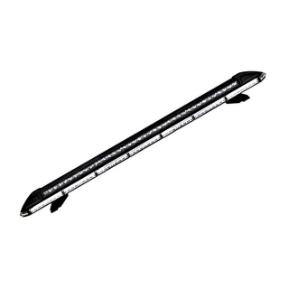
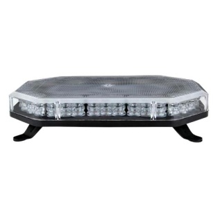
 Durite 0-443-51 4FT 4-bolt 12 or 12 Volts DC Amber LED light bar with stop, tail and directional indicator.

  • Voltage: 12V-24VDC (10V-30VDC)
  • Maximum power 68W
  • 10 Flash patterns
  • Waterproof to IP67
  • E-Marked, EMC R6 & R7, ECE R10 approved.

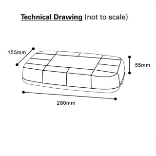
Dimensions

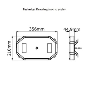
  • Depth: 326.5mm
  • Width: 1200mm
  • Height: 81mm

Mounting​ - For Translation Purposes

 Before proceeding with installation, plan all cable and wiring routing. Select the mounting location for the light bar on a flat, smooth surface and centre the unit across the width of the vehicle. The mounting location for the lightbar should be chosen so that the lightbar is level and visibility to traffic is optimised. Mounting should be such that there is no less than 12mm​ (1/2") clearance between the roof and the lightbar at any point.

  1. Insert the heads of the M8 mounting bolts into the opening at the end of the slots on the base of the lightbar. Loosely fasten mounting feet to base extrusion using M8 nuts and spring washers.
  2. Determine the location of the lightbar and the best route for wiring.
  3. Loosen the M8 nuts to allow the mounting feet to slide along the base. Place the lightbar on​ the vehicle in the determined location and slide the mounting feet into position. It is suggested that the feet be symmetrical and positioned near the curved edges of the roof, where the roof is the strongest.
  4. With the feet positioned, mark the location of the mounting hole centres on the roof. Remove the bar and drill the 8.5mm -10.0mm (11/39") mounting holes as marked. Note the centre​ distance between the mounting holes in a foot is 135mm (5 5/16").
  5. Insert M8 Coach bolts into the mounting feet (refer to diagram) and tighten the M8 nuts holding the feet to the base of the lightbar.
  6. Mount the light bar, with the bolts going through the holes drilled in step 4, routing the wire​ as planned in step 2 (refer to diagram). See the wiring section of this manual for further wiring instructions. Install washers and M8 Nyloc nuts, and secure the unit.

Notes For Consideration

  1. Larger wires and tight connections will provide longer service life for components. For high-current wires it is highly recommended that terminal blocks or soldered connections be used with heat shrink tubing to protect the connections. Do not use insulation displacement connectors.
  2. Route wiring using grommets and sealant when passing through compartment walls. Minimize the number of splices to reduce voltage drop. High ambient temperatures (e.g. under hood) will significantly reduce the current carrying capacity of wires, fuses and circuit breakers.
  3. Particular attention should be paid to the location and method of making electrical connections and splices to protect these points from corrosion and loss of conductivity.
  4. Ground termination should only be made to substantial chassis components, but preferably to the vehicle battery.
  5. Circuit breakers are very sensitive to high temperatures and will 'false trip' when mounted in a hot environment or operated close to their capacity.

Wiring Up The Lightbar

  1. Route wires from the vehicle positive (battery, alternator, fuse block) to the switch panel in the cab. Use suitable high-temperature vehicle cable if it passes through the engine compartment. Install an 10A fuse as close to the point of tapped power as possible.
  2. Connect the wires to the positive side of the additional control switch panel with quick-connect terminals or by soldering.
  3. After the light bar has been mounted, route the wiring harness into the vehicle to the switch panel location.
  4. Connect the wires of the light bar wiring harness to the switched side of each switch. See the wiring diagram for the wire colour key.
  5. Connect the light bar cable Black wire (-VE) to a solid ground connection on the vehicle (Ideally, direct to the battery negative terminal).
  6. Use cable ties and grommets to secure and protect all cables and wires.

 This unit is a safety device, and it must be connected to its own separate, fused power point to ensure its continued operation should any other electrical accessory fail. Do not wire in parallel with any other accessory. Disconnect the battery before wiring up the light bar to prevent accidental shorting, arcing and/or electrical shock.

Specifications

Type
Warning Lightbar with stop, tail and direction indicator
LED Colour
Amber/Red
Voltage
12-24VDC ((10-30VDC)
Maximum Power
68W
Fuse
10A
Current Draw 12VDC
5.9A
LEDs
DI: 24, Warning: 136 SMD - 10 Flash Patterns
Operating Temperature
-40°C to +65°C
Certificates
CE, E Mark R10 EMC, R6, R7.
Weight
9.8KG


Delivery
 
UK Mainland Postage

Delivery Options Our Free UK Mainland Postage and Packaging Service offers unbeatable value for money. The free UK Standard shipping is automatically applied to your shopping cart page with no additional cost when you reach the £50.00 minimum order value.

 We use Royal Mail Standard or Recorded Delivery for light, low-value orders and we use FedEx, UPS, Parcel Force, and other major courier services for larger and more valuable consignments.

 
International Consignments

 Our international customers will need to provide the exact Card Holder Address (Invoicee) as the first address for payment processing. Please note that PO Box addresses are not acceptable as delivery addresses by some couriers. All export orders must be placed and paid for online. Proforma Bank Transfer IBAN and SWIFT payment methods are available to create online.

Also Bought

Customer Feedback (0)
Leave a Review