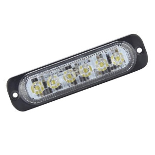
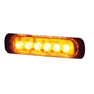
Durite 0-441-90 12 or 24 Volts DC super slim amber LED warning light with 7 flash patterns.
- Voltage 12V-24VDC (11V-32VDC)
- 6 x 3W LEDs
- 7 flash patterns
- Protected to IP69K
- ECE R65 (Class 2) R10 EMC, RoHS CE UKCA, and CAP 168 ICAO approved
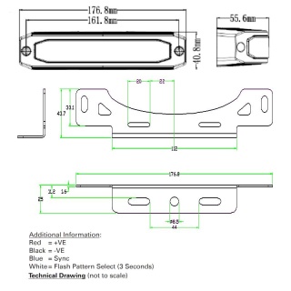
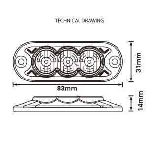
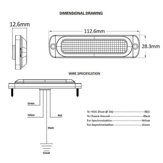
Dimensions
- Length: 118mm
- Width: 13mm
- Height: 13mm
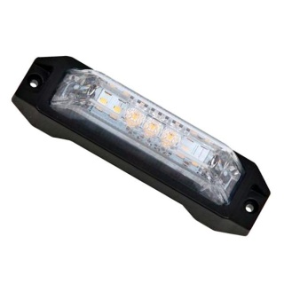
About the Slim Amber LED Warning Light
Durite super slim Amber LED warning light is an extremely versatile warning device. It is available in single and tricolour options to meet the needs of all applications, from amber safety and commercial vehicles to emergency services and covert vehicles. The lamp features a strong polycarbonate lens on an aluminium body to maximise protection from debris impact and absorb heat dispersion. This product also boasts major industry requirements such as IP69K for the toughest environments, EMC R10, ECE and R65 approvals and comes as standard with 7 flash patterns, including ICAO/CAP168 airport pattern. It includes an industry-first TD-Sync feature allowing users to synchronise and direct traffic with this inbuilt capability.
7 Flash Patterns Total
1. Quad 2. Triple 3. Double 4. Single 5. Quad/single 6. Quad/triple/double/single 7. CAP168
Mounting
- Place the unit against the mounting surface.
- Mark the areas where the mounting holes are to be drilled. Confirm that no vehicle parts could be damaged by the drilling process.
- Using a bit size for a no. 304 metal screw, drill two mounting holes, a 0.5-inch diameter. Wire passage hole(s) must also be drilled. Thoroughly de-burr all hole(s).
- Pass the wires through the hole(s) in the gasket and through the wire passage hole(s) in the mounting surface. Fix the light head to the mounting surface.
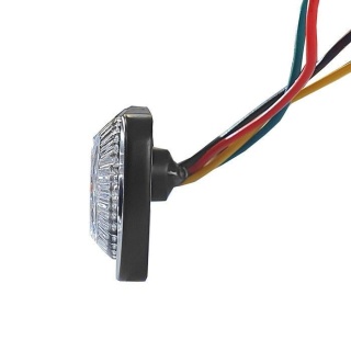
Wiring Colours
- Yellow: Synchronisation
- Brown: Pattern select
- Orange: Power (V2) 11-30V dc
- Green: Config
- Red: Power (V1) 11-30V dc
- Black: 0V ground
- Blue: DIM
Warnings and Instructions for Translation Purposes
Before using this unit, please read these instructions carefully. Take special care to follow the warnings and safety suggestions listed below. Keep these instructions for future reference.
Safety Warning
- Proper installation of this product requires the installer to have a good understanding of automotive electronics, systems and procedures.
- If mounting this product requires drilling holes, the installer MUST be sure that no vehicle components or other vital parts could be damaged by the drilling process. Check both sides of the mounting surface before drilling begins. Also, de-burr the holes and remove any metal shards or remnants.
- Do not install this product or route any wires in the deployment area of your airbag. Equipment mounted or located in the airbag deployment area will damage or reduce the effectiveness of the airbag or become a projectile that could cause serious personal injury or death. Refer to your vehicle owner’s manual for the airbag deployment area. The User/Installer assumes full responsibility for determining the proper mounting location, based on providing ultimate safety to all passengers inside the vehicle.
- Do not attempt to activate or control this device in a hazardous driving situation.
- This product contains either strobe light(s), halogen light(s), high-intensity LEDs or a combination of these lights. Do not stare directly into these lights. Momentary blindness and/or eye damage could result.
- All connections must use waterproof connectors, and any unconnected wires must be sealed to prevent water ingress via the wire core; failure to do this may result in premature failure and invalidate the warranty.
- Use only soap and water to clean the outer lens. The use of other chemicals could result in premature lens cracking (crazing) and discolouration. Lenses in this condition have significantly reduced effectiveness. Inspect and operate this product regularly to confirm its proper operation and mounting condition. Do not use a pressure washer to clean this product.
- It is recommended that these instructions be stored in a safe place and referred to when performing maintenance and/or reinstallation of this product.
- For this product to operate at optimum efficiency, a good electrical connection to the chassis ground must be made. The recommended procedure requires the product ground wire to be connected directly to the NEGATIVE (-) battery post.
Installation
Connecting the 0-441-90 directionals to a vehicle battery / power source requires the black wire to be connected to the negative (-ve) terminal, and either the red wire (V1), orange wire (V2) or V1 and V2 together (V3) to be connected to positive (+ve) terminal. Pattern and mode functions need to be set in the same manner as the primary red wire colour. Disconnect the red wire to set the secondary functions as desired. All 0-441-90 directionals are set to double flash pattern as default before leaving the factory.
To Set The Alternate Flash Mode
You can either set V1 to alternate against V2, or utilise the colour setting mode to combine an alternating feature on a single control line. If you want to keep them individually controlled: connect the red wire (or orange wire) to positive (+ve) and the black wire to negative (-ve) terminals on the power source. Hold the yellow wire to the negative (-ve) terminal on the power source. The 0-441-90 will turn from flashing to ‘steady burn’.
While holding the yellow wire on the negative (-ve) terminal, hold the brown wire to the positive (+ve) terminal. After 2 seconds, the unit will extinguish for 5 seconds, after which the 0-441-90 will start a quick succession of flashes. Remove the brown wire, the unit should now be flashing alternately to any 0-441-90 it synchronises with.
To Set The Flash Pattern
With the 0-441-90 powered on, the brown wire should be connected to positive (+ve) terminal from the power source momentarily, to change to the next pattern. Either touch the wire to positive (+ve) briefly, or connect via a momentary switch and press to change pattern.
To Set The DIM Function
Connect the blue wire to positive (+ve) at the power source to enable DIM (night) mode. The blue wire needs a constant connection to positive (+ve) to operate in this mode. The 0-441-90 will return to full brightness when the blue wire is disconnected.
To Synchronise 0-441-90
When the desired flash pattern and mode has been set, connect the yellow wires from each 0-441-90 together, this will ensure all 0-441-90 flash in synchronised format. Note: Do not apply yellow wires to positive (+ve). Do not attempt to sync DURITE products with any other manufacturer’s products.
Specifications
| Type | LED slim Amber warning lamp |
| Voltage | 12-24VDC (11-32VDC) |
| LEDs | 6 x 3W LEDs |
| Flash patterns | 7 |
| Material Construction | Polycarbonate |
| Operating temperature | -40 to +105 degree centigrade |
| Protection | IP69K |
| Certificates | ECE R65 (Class 2), R10 EMC, RoHS, CE, UKCA, CAP 168 ICAO |
| Weight | 38G |
.jpg)
.jpg)
.jpg)